Rules
Part of Electronics repair tools that earn a spot on the bench
Electronics Repair Problems and Fixes: When to Stop
Electronics repair problems and fixes: when to stop and what to do next for slipping drivers, stuck covers, connectors, adhesive, and reassembly faults.
What to take away
Electronics repair problems and fixes start with knowing when to stop.
- Stop when a tool slips, a panel bends, a battery moves, or a connector does not release as shown.
- Recheck the exact driver profile and size before attempting a damaged screw.
- Identify connector motion from the manual instead of pulling on the cable.
- Use only documented heat, solvent, depth, and cutting paths around adhesive.
- Preserve photos, screw positions, and symptoms so recovery does not create a second fault.
Repair damage often starts when normal resistance is mistaken for a request for more force. A screw may still be hidden. A cable may cross the opening edge. A latch may move sideways rather than upward. Adhesive may need controlled heat, not a deeper blade.
When the expected motion changes, stop and reset. Disconnect power when instructed, stabilize the device, and compare the current layer with the manual.
The driver slips in a screw
Remove force immediately. Clean the recess under magnification and inspect the bit. Confirm the profile, size, direction, and whether threadlocker or corrosion is involved. The profiles most repair kits need are Phillips and JIS cross-head, Torx and security Torx star, and Pentalobe. JIS cross-head screws look like Phillips, but a Phillips bit sits loosely in them and cams out more easily. Use a fresh bit that fills the recess and keep the shaft aligned with the screw. Bit fit and quality standards live in the electronics repair tools buying guide.
Wikipedia's screwdriver page names the mechanism: cross-head designs cam out, the bit riding up as torque rises. Every slip chews the recess more.
A matched profile, firm axial pressure, and an on-axis shaft keep the bit engaged. None of that guarantees removal of an already rounded head.
If the recess continues to deform, do not cycle through improvised glue, drills, cutting wheels, or sharp extractors beside a battery or board. A technician may be able to control debris and protect adjacent parts. Photograph the screw and note every attempted method.
The cover will not open
Count and map all removed screws. Check feet, labels, SIM trays, ports, keyboard areas, and hidden service covers only where the manual identifies them. Determine whether the cover uses clips, sliding hooks, adhesive, or a mixed system.
Place opening picks only at documented positions and depths. A pick inserted too far can cut a flex cable or cell. If the gap closes behind the pick, hold it with a plastic spacer rather than levering harder. New whitening, cracking sounds, glass lift, or battery movement are stop signs.
A cable connector will not release
First identify the type: press connector, friction fit, ZIF with a hinged flap, sliding lock, coaxial snap, board edge, or wire plug. Photograph its closed state. Release the lock with the specified nonconductive tool and move the connector body in the documented direction.
Never pull a cable by its flexible tail or wires. Do not pry against tiny board components. If a latch separates, keep every piece and stop repeated connection attempts. A torn pad or cracked socket can turn a module replacement into board repair. If damage does force a bigger part order, start with the OEM, aftermarket, and salvaged comparison.
Wikipedia's entry on the spudger describes it as a non-marring nylon tool made to separate pressure-fit components without damage during separation, which is exactly the property a metal blade lacks beside batteries, boards, and glass. Tool choice should follow the material and location, not just what fits into the gap.
Adhesive will not release
Confirm the adhesive type. Stretch-release strips require a low, steady pull along the device plane. Perimeter tape may require controlled warmth and a shallow cutting path. Foam can tear and leave residue. Liquid adhesive can spread into openings.
Use only the temperature, time, solvent, and applicator approved by the procedure. Remove or protect heat-sensitive parts as directed. Never heat a swollen, punctured, leaking, or unknown battery. Do not drip solvent onto a cell, display layers, microphone membrane, speaker, coating, or powered board.
If a strip breaks, expose a safe tail only by the documented method. Stop if the tool would pass beneath the cell or if the cell bends. Replacement adhesive needs clean, dry, aligned surfaces and intact release liners.
Static-control questions arise mid-repair
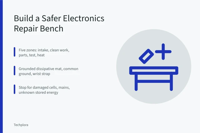
If a board has been exposed outside the prepared ESD area, stop handling it. Remove ordinary plastic packaging, control movement, and establish the approved mat, ground, and wrist-strap system described by the ESD control standard ANSI/ESD S20.20. Do not connect an improvised ground or wear a strap for hazardous-voltage work. The repair bench setup guide shows what a correct ESD system looks like.
Static damage may not leave a visible mark and may appear later as an intermittent fault. Record the exposure. Do not claim that an unrelated function test proves every component escaped damage.
A screw or bracket is missing
Do not substitute by appearance. Search the tray, mat, clothing, device edges, and floor with controlled lighting. Check photographs and count every compartment. Gently move an unpowered device only if the manual permits and no loose battery or fragile assembly can shift.
A longer screw in a shallow hole can damage a board, display, coil, or battery. A missing shield can change grounding, interference, heat spreading, or mechanical support. Order the exact item if it cannot be recovered. Receive it through the replacement part inspection checklist so profile and length are verified before installation.
The device fails after reassembly
Do not keep cycling power. Record the symptom, heat, sound, smell, screen behavior, and error. Disconnect power if safe. Review connectors, trapped cables, screw map, insulation, adhesive liners, shields, and forgotten transport films in reverse order.
Use one controlled test after each correction. If the fault includes severe heat, smoke, arcing, battery deformation, charging instability, or a damaged power circuit, stop and move to qualified service.
Common questions
Should I use a larger driver when a screw slips?
Test adjacent sizes without turning and choose the exact snug fit. The correct profile matters as much as size.
Can I pry a connector with metal tweezers?
Only if the service procedure explicitly calls for that tool and location. A nonconductive tool is usually safer around boards and batteries.
How much heat is safe for adhesive?
Use the limit and method for the exact device. There is no universal safe temperature, especially near batteries and displays.
Can a missing screw be replaced with one that fits?
Only when profile, diameter, thread, length, head, material, and function all match the specification.